6502 Logic Diagram 43++ Images Result
6502 Logic Diagram. 1.3 arithmetic and logic unit all arithmetic and logic operations take place within the alu including incrementing and decrementing internal registers (except the program counter). We agree to this nice of 6502 block diagram graphic could possibly be the most trending topic later than we portion it in google benefit or facebook.
Anonymous (january 3, 2011 1:55 pm) the ricoh (nes) processor was not strictly a 6502, in that it omitted decimal mode. Many components, many data paths 13 problem: With 2.5v would fill a complete article.
aldl wiring 1997 toyotum 4runner toyotum fortuner fuse box diagram digital tach wiring 4 wire schematic diagram 480 volt
90F 6502 Logic Diagram Ebook Databases
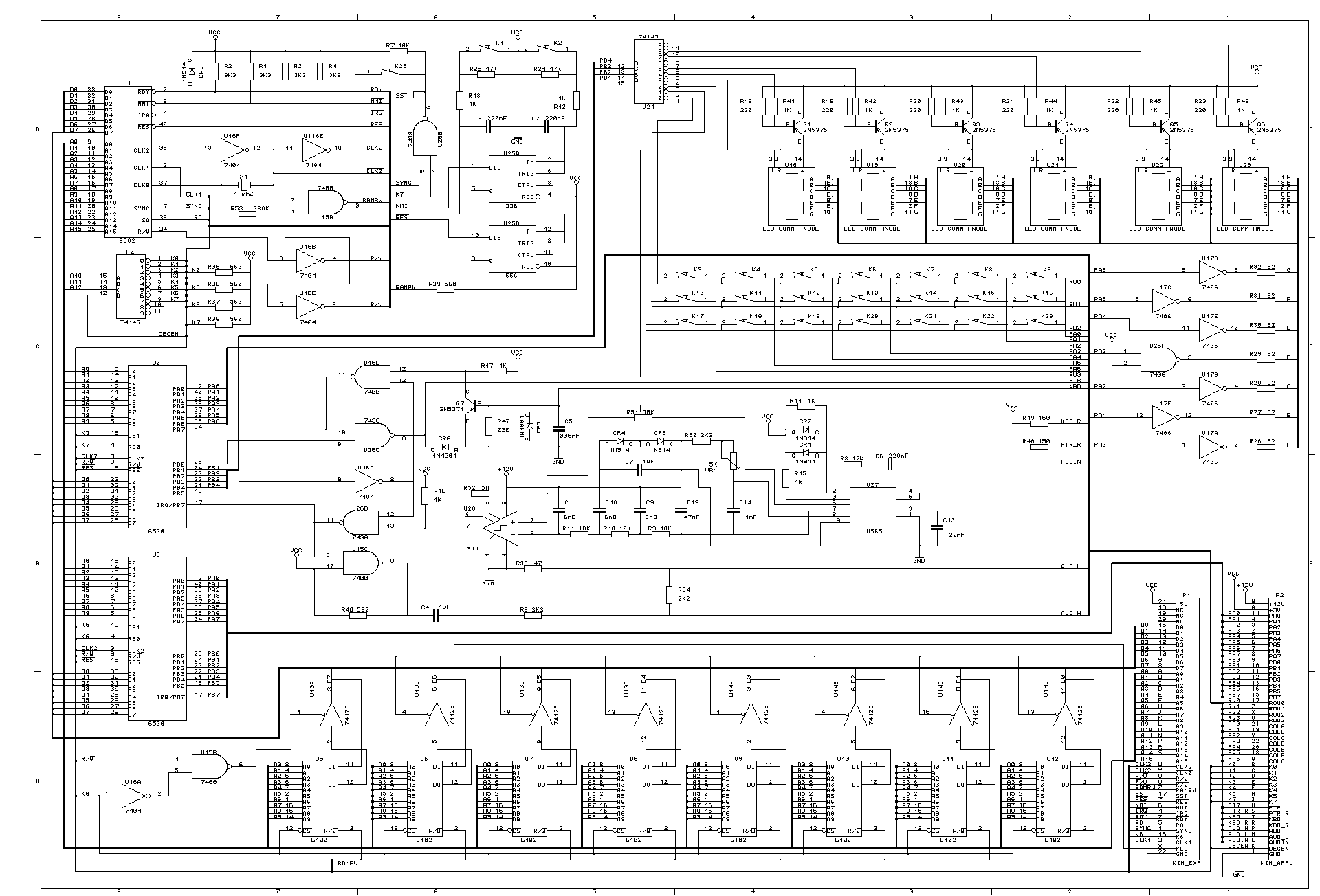
A simplified block diagram of the 6502 microprocessor kit is shown in figure 2. The voltage on any line programmed to be an output is determined by the corresponding bit in the output. Did first experiments with bc547/bc557 transistors at a 5v supply. Many components, many data paths 13 problem:

Source: 6502.org
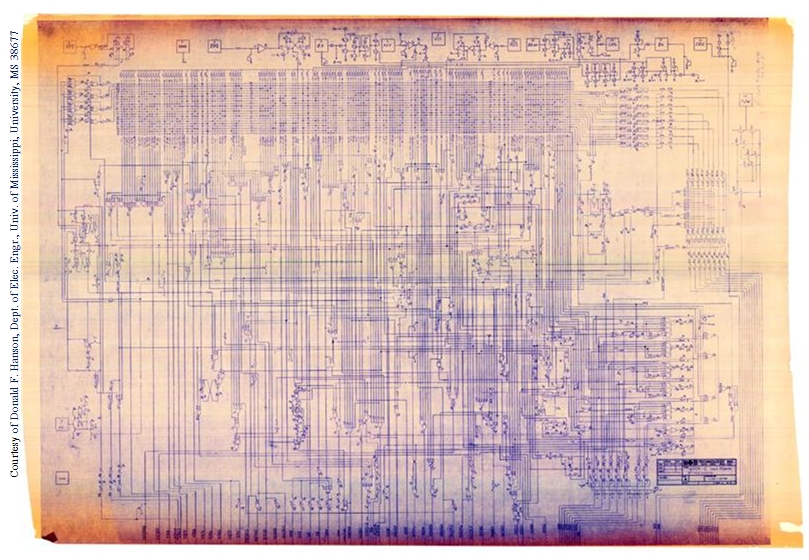
Alternatively, it may be installed. The memory and i/o spaces are selected by pld decoder. All circular paths are broken by inserting registers after every node. After all, this hybrid optimization is the true genius of the 6500. Mos technology, inc 650x microprocessor logic diagram engineering drawing.this document was generously contributed by benny pruden.

Source: stackoverflow.com
A logic one causes the corresponding pa line to act as an output. With a combination of the output signals the new xrdy signals is created. Did first experiments with bc547/bc557 transistors at a 5v supply. I have fully built the processor using the diagram and other resources as a reference in logisim, with the one exception being that i.

Source: stackoverflow.com
Smd bc847/bc857 in electrical parameters during experimentation. We agree to this nice of 6502 block diagram graphic could possibly be the most trending topic later than we portion it in google benefit or facebook. The voltage on any line programmed to be an output is determined by the corresponding bit in the output. Now to describe the logic gates, used.

Source: daggdroppe.se
In this article, i show how overflow is computed in the 6502 microprocessor at the transistor and silicon level. We agree to this nice of 6502 block diagram graphic could possibly be the most trending topic later than we portion it in google benefit or facebook. Mos technology, inc 650x microprocessor logic diagram engineering drawing.this document was generously contributed by.

Source: forum.6502.org
I have fully built the processor using the diagram and other resources as a reference in logisim, with the one exception being that i have combined the random control logic and decode rom into a single instruction rom, seen below. I was thinking about simulating it in a logic gate simulator, and the most i have found is a block.

Source: sites.google.com
In this article, i show how overflow is computed in the 6502 microprocessor at the transistor and silicon level. The nes was a similar story: Did first experiments with bc547/bc557 transistors at a 5v supply. Eprom stores the monitor program and sram stores the variables and stack memory. Dynamic nmos requires a large number of transmission gate transistors that are.

Source: forum.6502.org
Mos technology, inc 650x microprocessor logic diagram engineering drawing.this document was generously contributed by benny pruden. We aim to present our work in a visual, intuitive manner for education and inspiration, and to serve as a solid verifiable reference for classic computer systems. A logic zero in a bit of the data direction register (ddra) causes the corresponding line of.

Source: retrocomputing.stackexchange.com
6502 interrupt and bus 23 september 2019. The nes was a similar story: A simplified block diagram of the 6502 microprocessor kit is shown in figure 2. Anonymous (january 3, 2011 1:55 pm) the ricoh (nes) processor was not strictly a 6502, in that it omitted decimal mode. Did first experiments with bc547/bc557 transistors at a 5v supply.

Source: electronics.stackexchange.com
Now to describe the logic gates, used in mt15. With 2.5v would fill a complete article. After all, this hybrid optimization is the true genius of the 6500. A logic zero in a bit of the data direction register (ddra) causes the corresponding line of the pa port to act as an input. With a combination of the output signals.

Source: electronics.stackexchange.com
With a combination of the output signals the new xrdy signals is created. I am working off of hanson's block diagram to build my subset. I am currently trying to determine how exactly the instructions are decoded into the control lines. With 2.5v would fill a complete article. Although the 6502 alu only has five elements (add, or, xor, and,.

Source: forum.6502.org
Point is, that pcb size is a primary cost factor. The main ic used for the generation is the shift register 74ls164. Increasing number of components { multiple registers { program counter { stack pointer { arithmetic logic unit { memory more components, more data paths some components are outside the cpu { main. Smd bc847/bc857 in electrical parameters during.

Source: visual6502.org
Main parts are 6502 cpu, memory chips eprom and sram. How exactly does the 6502 decode the program instructions into control lines? Point is, that pcb size is a primary cost factor. All circular paths are broken by inserting registers after every node. John lazzaro (january 3, 2011 1:54 pm) this post has been removed by the author.

Source: righto.com
Did first experiments with bc547/bc557 transistors at a 5v supply. The main ic used for the generation is the shift register 74ls164. The 6502 was revolutionary in its time, and widely adopted in early home computers and gaming consoles. A logic one causes the corresponding pa line to act as an output. Smd bc847/bc857 in electrical parameters during experimentation.

Source: forum.6502.org
Smd bc847/bc857 in electrical parameters during experimentation. The nes was a similar story: Here are a number of highest rated 6502 block diagram pictures on internet. We aim to present our work in a visual, intuitive manner for education and inspiration, and to serve as a solid verifiable reference for classic computer systems. 6502 interrupt and bus 23 september 2019.

Source: 6502.org
6502 diagram 12 philipp koehn computer systems fundamentals: The voltage on any line programmed to be an output is determined by the corresponding bit in the output. In this article, i show how overflow is computed in the 6502 microprocessor at the transistor and silicon level. Mos technology, inc 650x microprocessor logic diagram engineering drawing.this document was generously contributed by.

Source: retrocomputing.stackexchange.com
The nes was a similar story: With a combination of the output signals the new xrdy signals is created. (kind of like how c. Did first experiments with bc547/bc557 transistors at a 5v supply. Smd bc847/bc857 in electrical parameters during experimentation.

Source: forum.6502.org
Here we'll slowly but surely present our small team's effort to preserve, study, and document historic computers. Anonymous (january 3, 2011 1:55 pm) the ricoh (nes) processor was not strictly a 6502, in that it omitted decimal mode. 6502 interrupt and bus 23 september 2019. One of my main resources is hanson's block diagram. With 2.5v would fill a complete.

Source: visual6502.org
(kind of like how c. Many components, many data paths 13 problem: The voltage on any line programmed to be an output is determined by the corresponding bit in the output. Elegans is used as a model organism for biology) We aim to present our work in a visual, intuitive manner for education and inspiration, and to serve as a.

Source: forum.6502.org
We identified it from reliable source. And numerous potential feedback loops in the data path. I was thinking about simulating it in a logic gate simulator, and the most i have found is a block diagram (that i've read may be inaccurate) i would like to use the 6502 for a class on beginner chip architecture. The monster 6502 uses.

Source: grappendorf.net
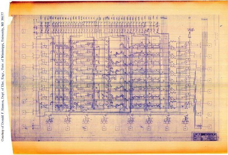
In the diagram below, there are two parts, the decode rom and the random control logic. Eprom stores the monitor program and sram stores the variables and stack memory. Many components, many data paths 13 problem: The memory and i/o spaces are selected by pld decoder. A logic zero in a bit of the data direction register (ddra) causes the.