Relay Logic Diagram Example 46++ Images Result
Relay Logic Diagram Example. Diagram comparison of logic symbols 18 figure 8: When the start button is pressed, the control relay energizes and its associated contacts change state.
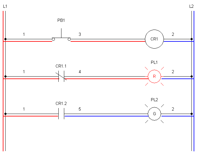
Relay logic provides you with a guide for using ncd relay controllers, and how they can be wired for many types of applications. When the start button is pressed, the control relay energizes and its associated contacts change state. In this circuit, rung 1 contains one push button (initially off) and one control relay.
wiring diagram for electric heater proces flow diagram t 16949 2001 yamaha royal star venture wiring diagram 6 electrical schematic wiring diagram
Relay Logic Diagram Example Complete Wiring Schemas
Use relay logic to control the forward or reverse direction of motors. An example of a ”ladder logic” diagram is shown here: “stop button” or plc input i0.1. Rung 2 contains one push button (initially on) and one pilot lamp.

Source: destee.com
Example b of single line diagram 21 figure 11: In this circuit, rung 1 contains one push button (initially off) and one control relay. Continuation of example b of an ac. Figure 1 shows a typical relay logic diagram. This schematic diagram represents a type of programming frequently referred to as ladder logic by industrial electricians.

Source: wadeinstruments.com
In this circuit, a stop/start station is used to control two pilot lights. When the start button is pressed, the control relay energizes and its associated contacts change state. Plc input and output switch. Ladder logic diagram example 2 thought process identify the output: A type of electrical diagram convention optimal for representing electromechanical relay circuits is the ladder logic.

Source: chegg.com
Traditional ladder diagram plc ladder diagram x5 x6 y3 y3 y3 x5 y3 x6 when the above circuit. Figure 1 shows a typical relay logic diagram. An example of a ladder logic diagram is shown here: In a “ladder” diagram, the two poles of the power source are drawn as vertical. Rung 2 contains one push button (initially on) and.

Source: wiring89.blogspot.com
First we understand what is no and nc point. A type of electrical diagram convention optimal for representing electromechanical relay circuits is the ladder logic diagram. Example b of single line diagram 21 figure 11: Each parallel circuit branch is represented as its own horizontal rung between the two vertical rails of the ladder. Traditional ladder diagram plc ladder diagram.

Source: electrical-engineering-portal.com
Protection settings can also be documented to Relay logic provides you with a guide for using ncd relay controllers, and how they can be wired for many types of applications. To understand and create rlc, we must have to know about the basic element. When the start button is pressed, the control relay energizes and its associated contacts change state..

Source: wiring89.blogspot.com
Ladder logic diagram example 2 thought process identify the output: Rung 2 contains one push button (initially on) and one pilot lamp. Electromechanical relays may be connected together to perform logic and control functions, acting as logic elements much like digital gates (and, or, etc.). Logic schematics can be drawn to illustrate how different protection elements are wired. Example b.

Source: instrumentationtools.com
Line relay symbol for substation single line diagram 18 figure 10: Relay logic is a method of operating industrial electrical circuits with the help of relay and contacts. The green pilot light is now on and the red lamp is off. Example b of an ac schematic 23 figure 13: Relay logic provides you with a guide for using ncd.

Source: electrical-engineering-portal.com
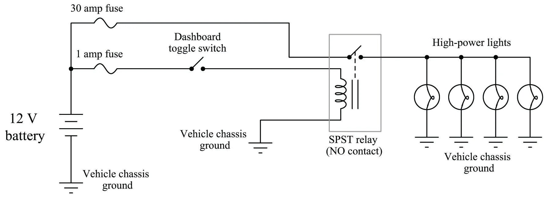
A very common form of schematic diagram showing the interconnection of relays to perform these functions is called a ladder diagram. A very common form of schematic diagram showing the interconnection of relays to perform these functions is called a ladder diagram. Relay logic’s ladder diagrams used physical contacts, coils, switches, and lots of other devices for every single function.

Source: pinterest.com
Early relay diagram symbols were literal interpretations of physical relay panels. An example of a ”ladder logic” diagram is shown here: Plc based objects counting system circuit diagram. Section from substation single line 18 figure 9: Close circuit of tie relay trip and close circuits for both mains and the tie would also be illustrated and documented.

Source: electrical-engineering-portal.com
A type of electrical diagram convention optimal for representing electromechanical relay circuits is the ladder logic diagram. Diagram comparison of logic symbols 18 figure 8: Relay logic’s ladder diagrams used physical contacts, coils, switches, and lots of other devices for every single function on a machine. Example write the state equation for a motor starting control described in the state.
Source: wiring89.blogspot.com
When the start button is pressed, the control relay energizes and its associated contacts change state. The green pilot light is now on and the red lamp is off. L1 l2 indicator lamp heater on heater master power control high pressure switch relief solenoid Rung 2 contains one push button (initially on) and one pilot lamp. Protection settings can also.

Source: pinterest.com
As time went on, changes to logic programming and mechanical failures caused engineers to look for a digital alternative. Each parallel circuit branch is represented as its own horizontal “rung” between the two vertical “rails” of. The two parts of a relay are both shown in this diagram. Figure 1 shows a typical relay logic diagram. A very common form.

Source: circuitdigest.com
These are basic element for rlc. In a “ladder” diagram, the two poles of the power source are drawn as vertical. Close circuit of tie relay trip and close circuits for both mains and the tie would also be illustrated and documented. Example a of an ac schematic 22 figure 12: An example of a ”ladder logic” diagram is shown.

Source: wiringdiagrams3.blogspot.com
Logic schematics can be drawn to illustrate how different protection elements are wired. “start button” or plc input i0.0. Example a of an ac schematic 22 figure 12: Ladder logic diagram example 2 thought process identify the output: To understand and create rlc, we must have to know about the basic element.

Source: electrical-engineering-portal.com
Simple ladder logic examples of startstop of relay. The green pilot light is now on and the red lamp is off. A very common form of schematic diagram showing the interconnection of relays to perform these functions is called a ladder diagram. In this circuit, a stop/start station is used to control two pilot lights. Simple start/stop ladder logic relay.

Source: wadeinstruments.com
An example of a ”ladder logic” diagram is shown here: Relay logic is a method of operating industrial electrical circuits with the help of relay and contacts. Example a of an ac schematic 22 figure 12: Diagram comparison of logic symbols 18 figure 8: In a “ladder” diagram, the two poles of the power source are drawn as vertical.

Source: instrumentationtools.com
A type of electrical diagram convention optimal for representing electromechanical relay circuits is the ladder logic diagram. An example of a ”ladder logic” diagram is shown here: A type of electrical diagram convention optimal for representing electromechanical relay circuits is the ladder logic diagram. Logic schematics can be drawn to illustrate how different protection elements are wired. First we understand.

Source: wiringschemas.blogspot.com
“stop button” or plc input i0.1. Figure 1 shows a typical relay logic diagram. Close circuit of tie relay trip and close circuits for both mains and the tie would also be illustrated and documented. To understand and create rlc, we must have to know about the basic element. Relay logic’s ladder diagrams used physical contacts, coils, switches, and lots.
Source: wiring89.blogspot.com
Relay logic relay logic, ladder logic, and ladder diagrams all refer to the way we organize an electrical circuit. Each parallel circuit branch is represented as its own horizontal rung between the two vertical rails of the ladder. Diagram comparison of logic symbols 18 figure 8: When the start button is pressed, the control relay energizes and its associated contacts.

Source: wiring89.blogspot.com
Relay logic is a method of operating industrial electrical circuits with the help of relay and contacts. Early relay diagram symbols were literal interpretations of physical relay panels. As time went on, changes to logic programming and mechanical failures caused engineers to look for a digital alternative. Electromechanical relays may be connected together to perform logic and control functions, acting.